Forum Replies Created
-
AuthorPosts
-
j_flandersParticipant
If there’s a fusible resistor in there it can be fixed, but in those cases the led usually doesn’t come on and nothing but the bypass works.
Otherwise it will be hard. But it can be a fun challenge if you like doing this kind of stuff.
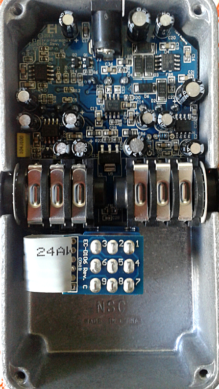
Apart from a few caps it’s all smd…I see it costs around 70 euros new. It will cost (a lot) more than that to get it repaired by a technician.
Maybe you can post some clear photos of the pcb?Here’s a blurry one I found online.
 j_flandersParticipant
Wow, nicely done. Now I see it’s all wood as well.
In case you experience too much noise, or interference from the outside, you could glue some copper or aluminum foil to the entire inside. That will work as a shield (if it’s connected to ground)
j_flandersParticipantI think it looks great but can’t tell for sure as the pictures are so tiny (about an inch wide)
The thumbnails are even bigger than the image when clicked.Edit: I see there’s a limit of 75kb per attachment. Seems like a limit from 1975.
The smileys are from that era as well. lolj_flandersParticipantQuote:Also just tried to put a 100pf cap between base and collector on Q2. No results.
How about the ele cap, what might that change ?
PaulA small cap between collector and base reduces gain for (very) high frequencies. In general it will prevent fizzy top end distortion. But if the cap is (too) small or the gain rather low the effect is very subtle or inaudible.
Sometimes people use it to simulate germanium transistors when using silicon transistors. Germanium transistors have this extra capacitance internally. You can replicate it on silicons by adding it externally.Normally that big electro cap across the power rails is used for power filtering (removing ripple) but in battery operated pedals there’s no ripple to remove, so I guess the only reasonable explanation is this one by PRR:
https://www.diystompboxes.com/smfforum/index.php?topic=113734.msg1053703#msg1053703
and this one by Teemuk:
https://www.diystompboxes.com/smfforum/index.php?topic=113734.msg1054057#msg1054057j_flandersParticipantQuote:The diodes in that old Muff Fuzz are very small like 1N914, so I guess they are germanium.
The circuit in that little box was made very tight, the diodes were soldered with the leads “nonexistent”.
Surprised they did not fail.Hehe ok.
Yeah on most photos I find online they look like 1N4148 or 1N914 but just wanted to check with yours.
1N914 is silicon though, but that’s ok.j_flandersParticipantThanks a lot for the schematic!
Any idea what the original diodes were? (silicon or germanium?)Quote:It has a Positive ground so, I guess you are not supposed to use it at the same time with other Negative ground devices.You can use it together with negative ground devices but you cannot daisychain them from the same power supply. It needs its own, battery or adapter.
Apart from the transistors, and diodes perhaps, most schematics online look to be accurate.
It’s a silicon Fuzz Face variant btw (but it has no bypass cap on the emitter of Q2 and therefor a lot less gain, but it has (clipping?) diodes on the output.
j_flandersParticipantQuote:I have not found the circuit of my muff fuzz on the web, but I have drawn it.I’d love to see (and build) it. If you cannot post schematics here maybe you can send it in a private message?
j_flandersParticipantAre any of the online schematics correct when compared to your Muff Fuzz (apart from the resistor mistake)?
If so could you please post a link.I love my Double Muff btw but the circuit is slightly different from being just two Muff Fuzzes cascaded as it is being advertised. Well, at least if I go by the Muff Fuzz schematics I find online.
j_flandersParticipantMaybe you can try it on its own power supply (keeping the other pedals daisy chained if you want).
j_flandersParticipantQuote:It does, it works as is expect until the click, at which point out switches to low. Almost like there’s a latch or something in the pot that’s goneThe ‘tab’ that limits the rotation probably broke of.
http://www.geofex.com/article_folders/potsecrets/potscret.htm
[img]http://www.geofex.com/article_folders/potsecrets/pot4.JPG[/img]Trying to repair the ‘broken’ pot is doable but a gamble as there’s a good chance you will break it beyond repair and then what?
Since it still works, I would just use it as it is. Now you can go from min to max or vice versa with only 60° rotation instead of 300°.Happy hunting for a new pot.
Normally, for these niche items I’d suggest Smallbear but even he doesn’t have them for sale, so it’s going to be really hard to find one.
He does list a pot you could use after a tedious amount of modding to both pot and enclosure:
http://smallbear-electronics.mybigcommerce.com/poteniometer-for-russian-big-muff-work-alike/
http://smallbear-electronics.mybigcommerce.com/electro-harmonix-sovtek-spares-1/?sort=featured&page=3
[img]https://cdn10.bigcommerce.com/s-sxoup5r/products/3762/images/6147/Russian_BMP_Pot__93201.1523243561.1280.1280.jpg?c=2[/img]With the volume up, the pedal should not be quiet or any quieter than other Big Muff Pi’s. So there might be other issues. This has nothing to do with old or new.
Black Russian BMP uses linear pots though, so you have to turn the volume up more, compared to a lot of other versions of the BMP which use log pots, to get the same output volume.
But with volume at max on both, they’re pretty much equally loud.j_flandersParticipantOr read my reply at DIYstomboxes.com (which doesn’t send notifications when there are new replies)
https://www.diystompboxes.com/smfforum/index.php?topic=123653.0j_flandersParticipantLots of pictures of the Rams head inside here:
http://www.kitrae.net/music/big_muff_history1.htmlj_flandersParticipantThe LPB1 has a very low input impedance, similar to a Fuzz Face, not *as* low but low enough to load down your guitar pickups.
The disadvantage (similar to a Fuzz Face) is that it may not sound good or as intented when it’s not directly connected to your guitar’s pickups but to the output of another guitar pedal.
Even a disengaged pedal with a buffer (any Boss pedal) in front of the LPB1 may make it sound too harsh, garbled and gritty.
You’ll experience the same thing with a Double Muff, Muff Fuzz or Muff Overdrive. Not so much with a Big Muff (despite the similar low input impedance) because of the series resistor at the input.
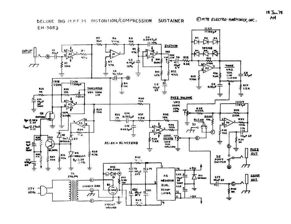
j_flandersParticipantschematic is in this thread:
https://www.ehx.com/forums/viewthread/7000/
Edit:
It’s on photobucket.
In case you cannot see it, here’s a repost:
-
AuthorPosts
")